Featured Projects
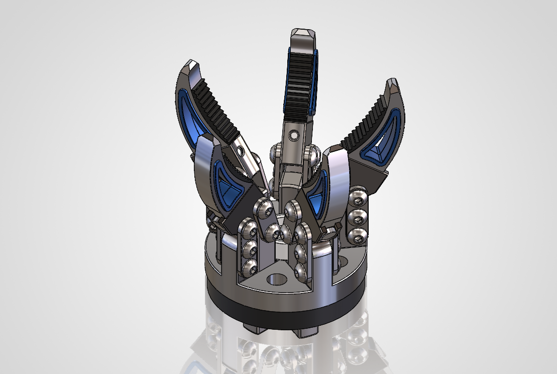
Project 1 – Structural Optimization of a Robotic Gripper Finger Using Static and Fatigue FEA
Project Overview
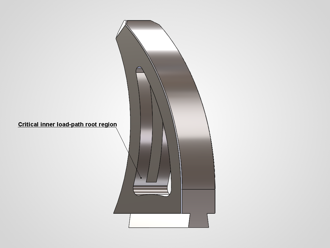
This project focused on the structural optimization of a robotic gripper finger using static and fatigue finite element analysis. The baseline geometry was evaluated under a 300 N load, and the highest stress concentration was identified at the inner load-path root region. A second design iteration introduced local slot-corner relief fillets and increased the critical root fillet radius to smooth the stress flow. Compared with the baseline, the final design reduced peak von Mises stress by 13.5%, equivalent elastic strain by 13.9%, and total deformation by 3.2%. Fatigue analysis under zero-based cyclic loading (0–300 N) showed that both designs remained in the high-cycle regime, but the optimized version improved the minimum fatigue safety factor by 15.7%. The study shows how small local geometry refinements can improve structural response without changing the overall load case.
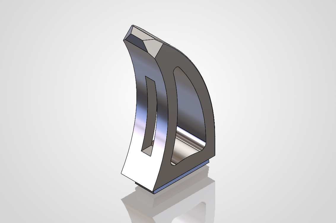
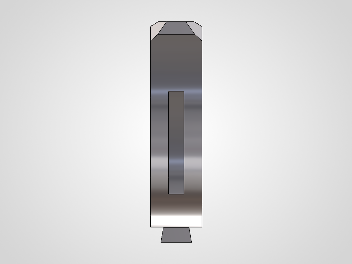
V1 Baseline
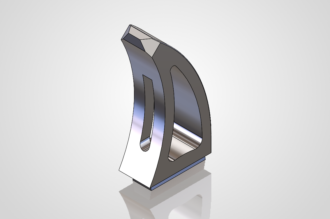
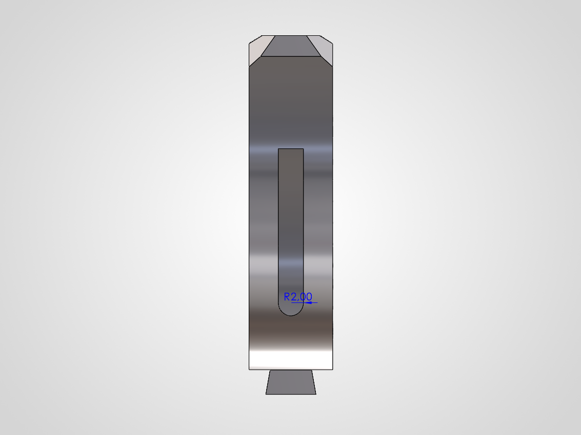
V2 Final Iteration
Tools: SolidWorks, ANSYS Mechanical
Objective
The aim of the study was to reduce stress concentration in the critical root region of the gripper finger, lower elastic strain, and improve fatigue behaviour under the same loading and boundary conditions. The focus was not on changing the global form of the part, but on refining a few local geometric transitions along the load path.
Scope and Limitation
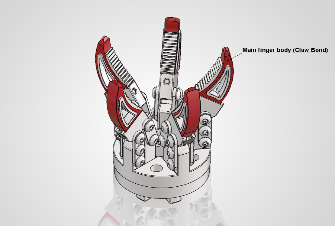
The study focused on the primary load-bearing finger body. Mating components were not fully reworked in this iteration, since the scope of the study was limited to comparative structural and fatigue response of the main part under identical boundary conditions.
Model and Analysis Setup
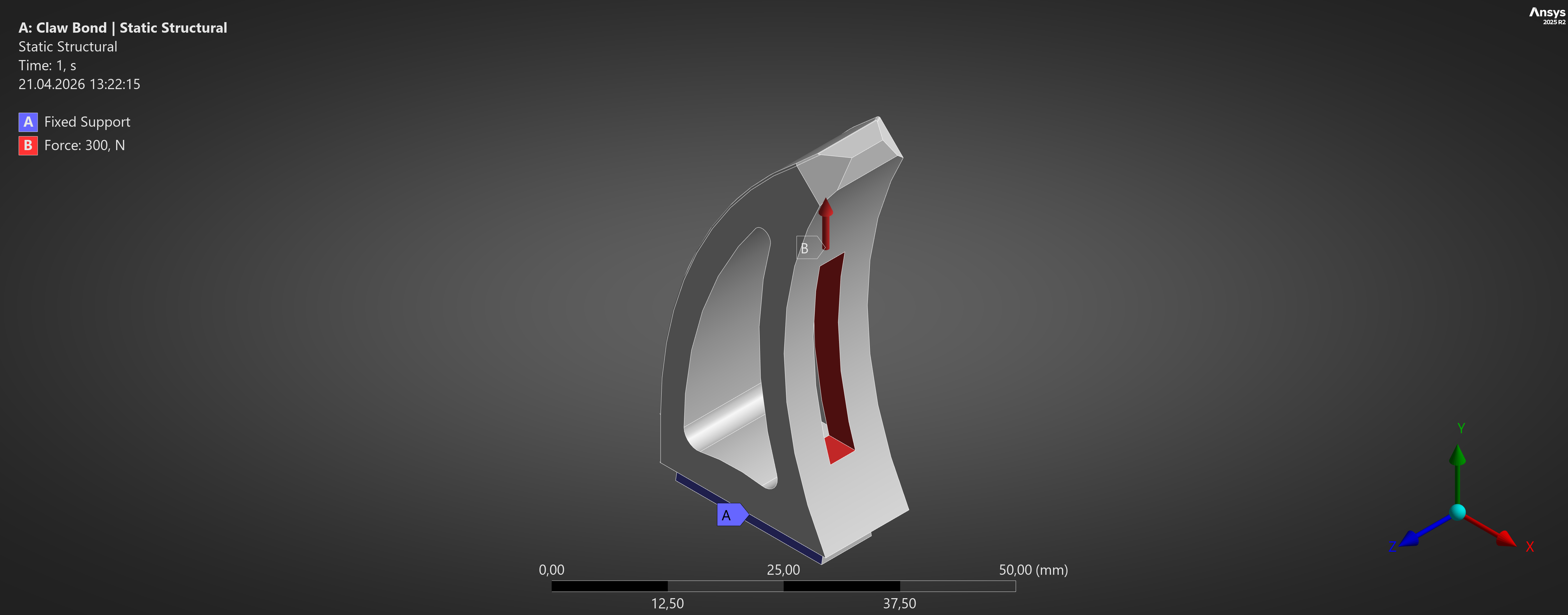
The part material was defined as Aluminum 6061-T6. Structural performance was evaluated in ANSYS using both Static Structural and Stress-Life Fatigue analysis. A 300 N load case was applied to the finger, and fatigue was assessed using zero-based cyclic loading (0 → 300 N → 0) with Goodman mean stress correction and Equivalent (von-Mises) stress as the fatigue stress component.
Design Versions
V1 – Baseline
The first version was the original finger geometry.
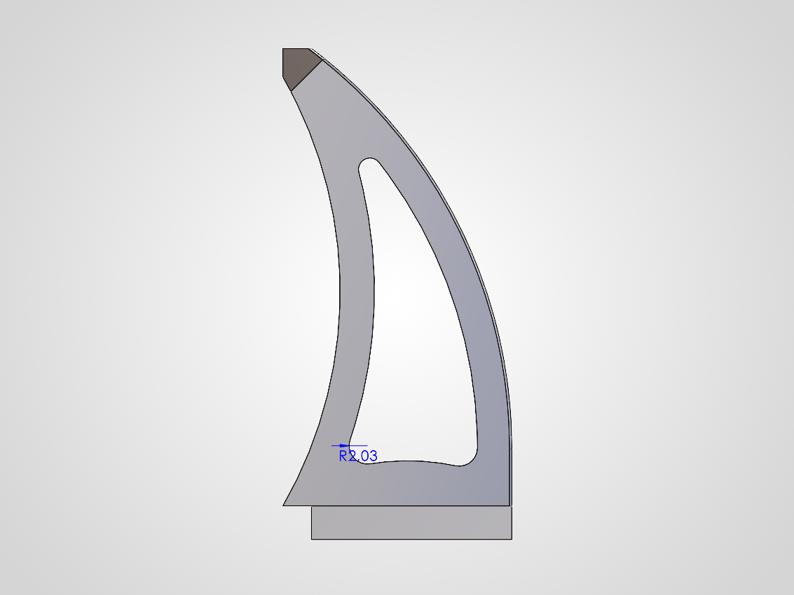
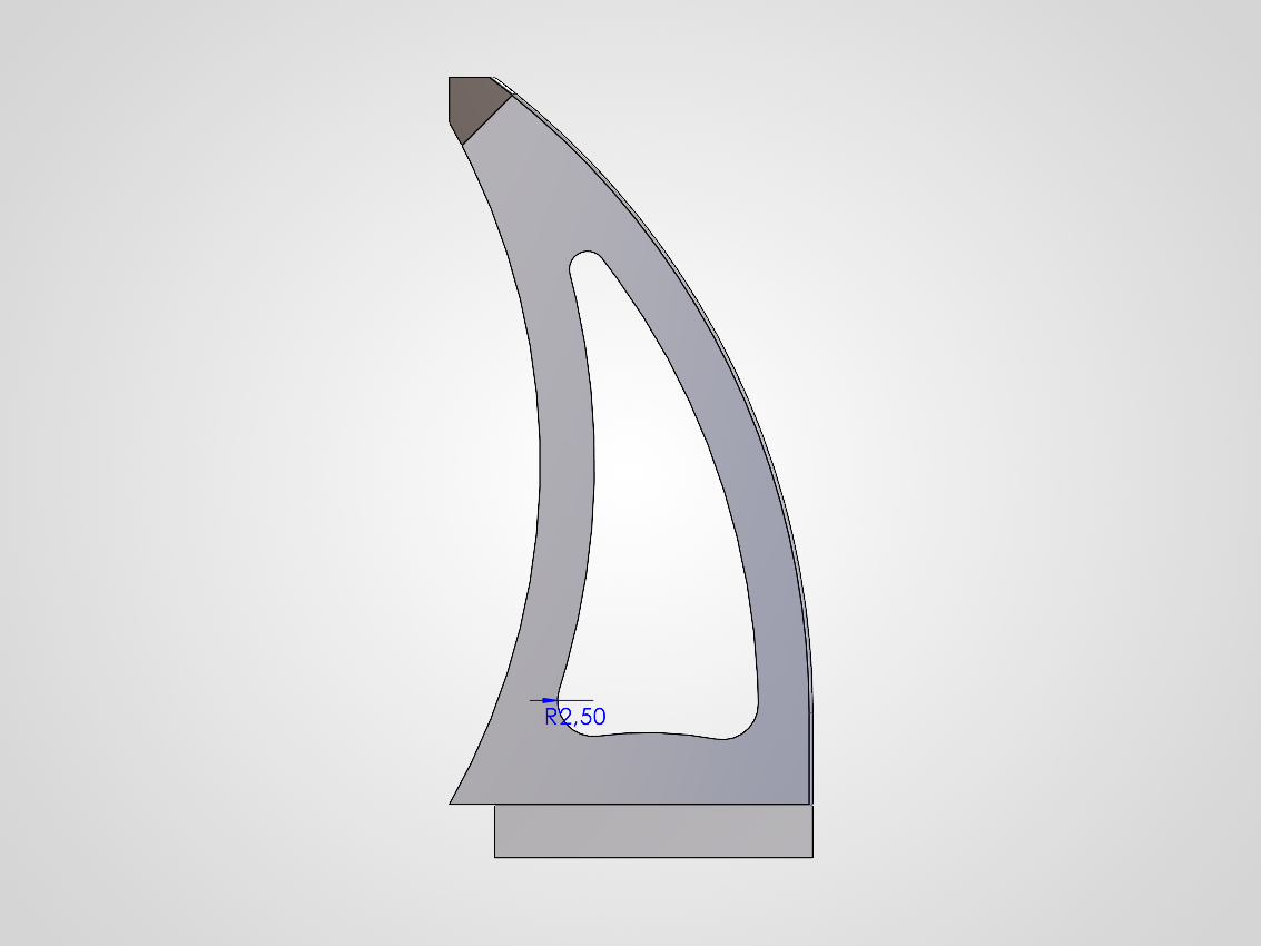
V2 – Final Iteration
Two local geometry refinements were introduced in the final version: R2.0 mm fillets were added to the two lower slot corners. The critical inner root fillet was increased from approximately R2.03 mm to R2.5 mm. These modifications were selected to smooth the local load path, reduce abrupt stress transitions, and relieve the hotspot identified in the baseline analysis.
V1 Baseline
V2 Final Iteration
Static Analysis Results
The redesigned geometry produced a measurable improvement under the same 300 N load case. Peak stress, equivalent elastic strain, and deformation all decreased in the final version.
Static Results Table
| Metric | V1 Baseline | V2 Final | Change |
|---|---|---|---|
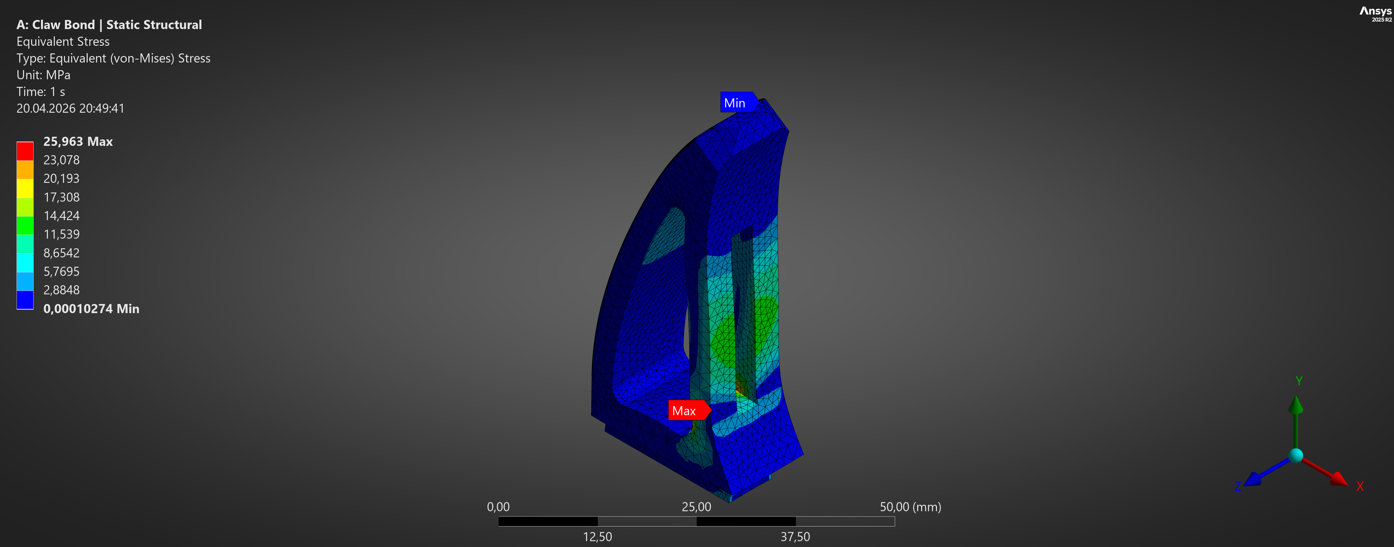
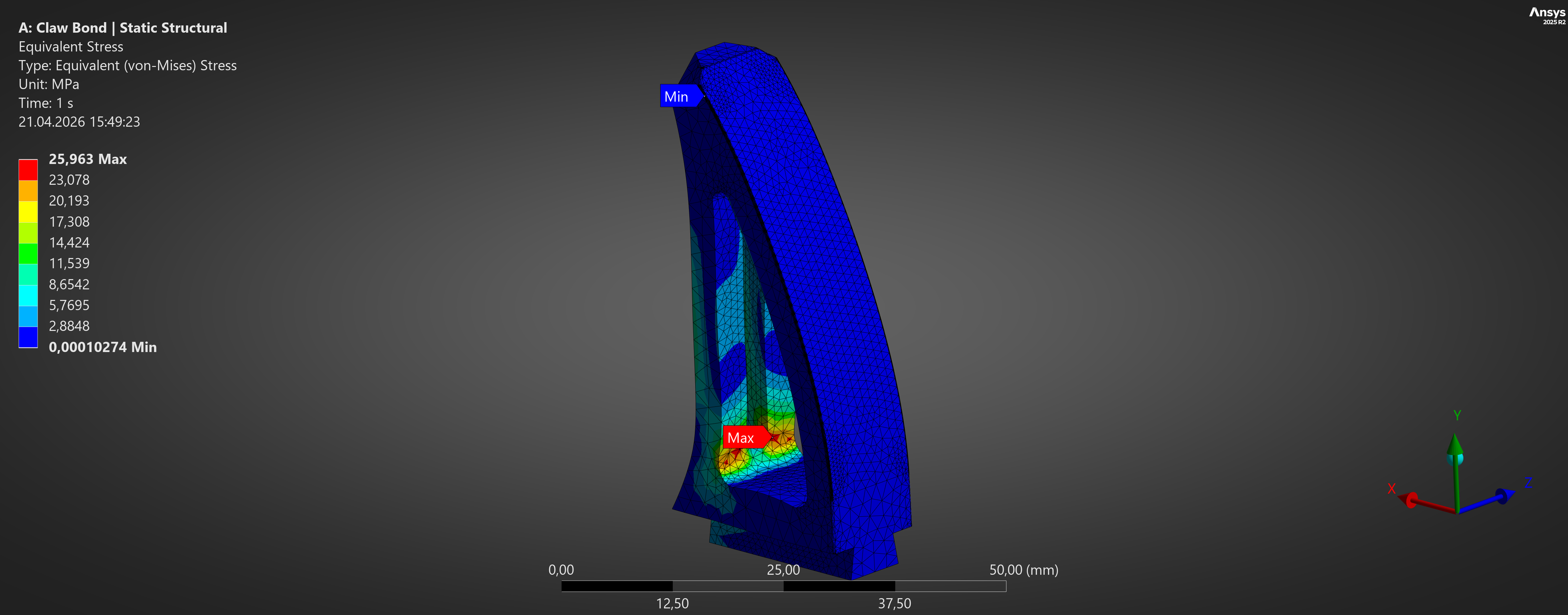
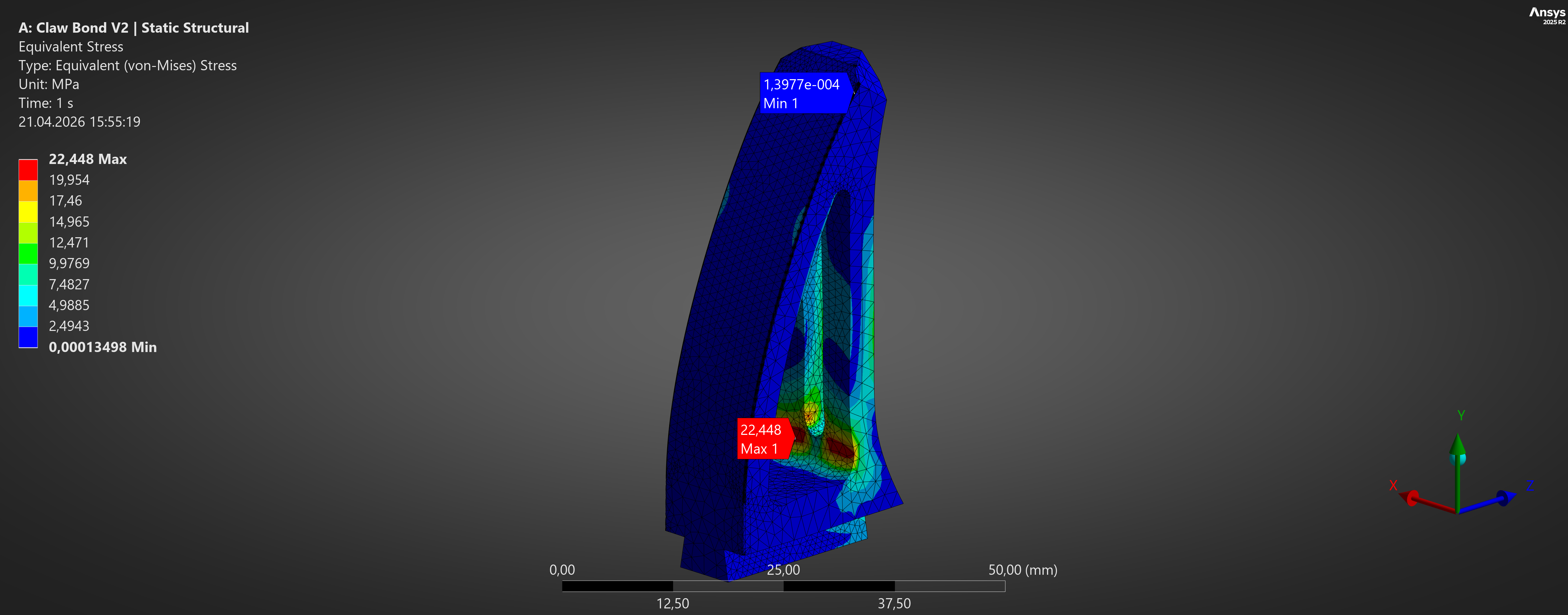
| Equivalent Stress | 25.963 MPa | 22.448 MPa | -13.54% |
| Total Deformation | 0.008805 mm | 0.008524 mm | -3.19% |
| Directional Deformation (Y) | 0.006646 mm | 0.006353 mm | -4.41% |
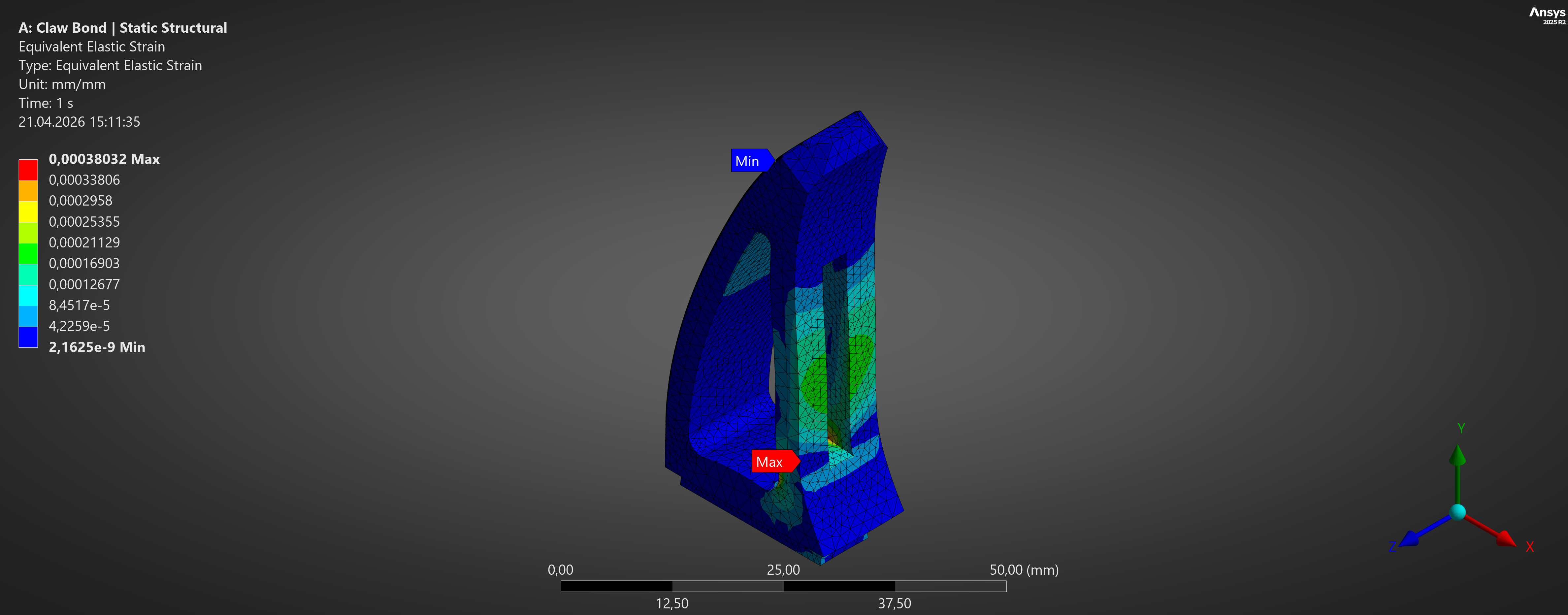
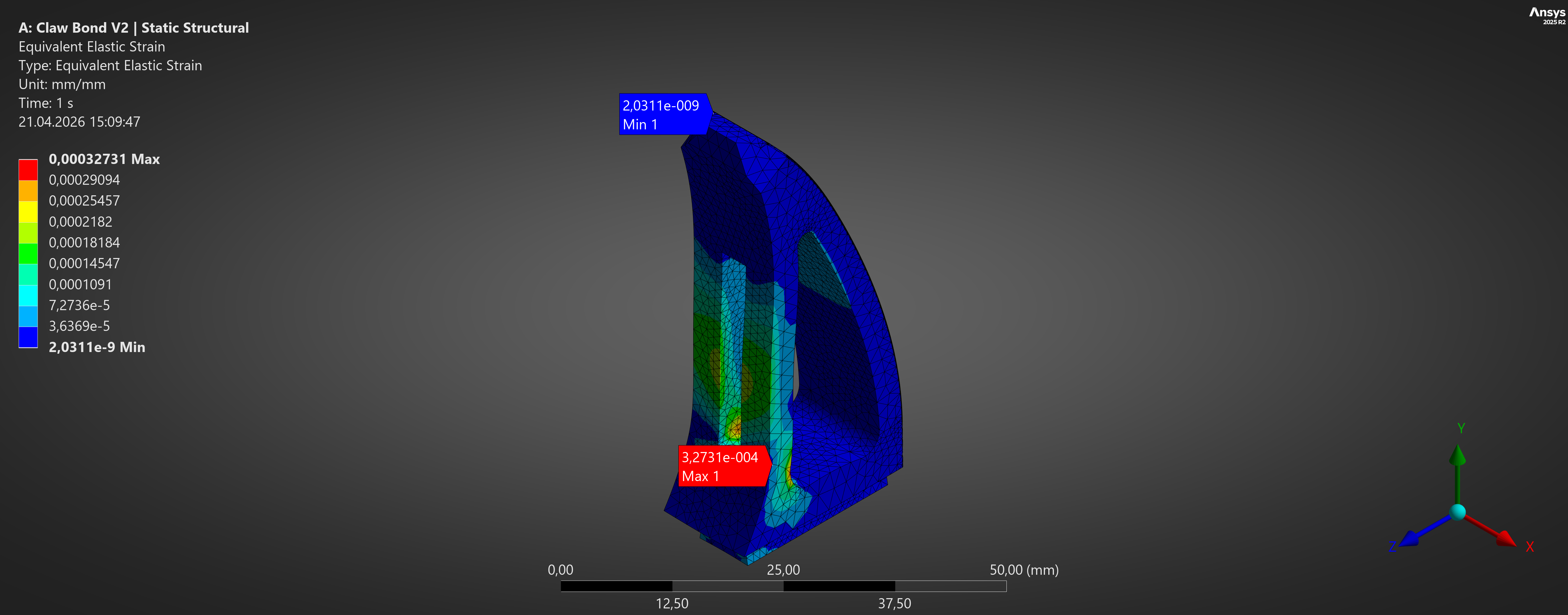
| Equivalent Elastic Strain | 0.00038032 | 0.00032731 | -13.94% |
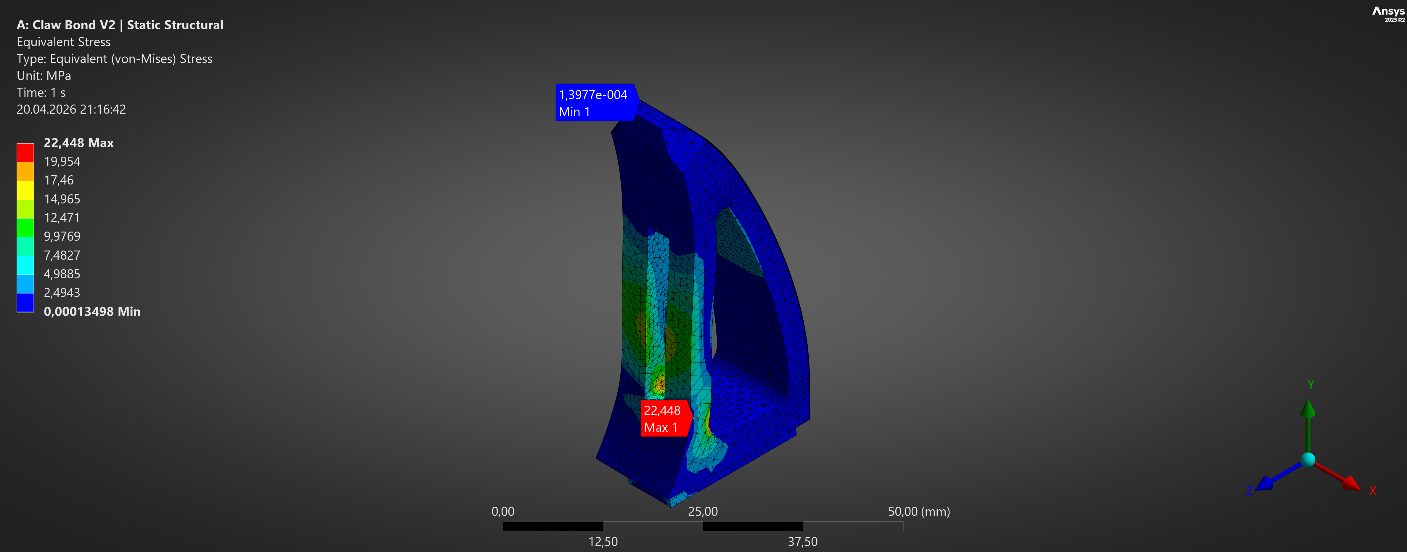
The final V2 redesign reduced peak von Mises stress and equivalent elastic strain while also slightly decreasing deformation under the same 300 N load case. Although both versions remained in a high-cycle fatigue range of approximately 1e8 cycles, V2 increased the minimum fatigue safety factor by about 15.7%, making it the stronger final design candidate.
V1 Baseline Equivalent (von-Mises) Stress Result
V2 Final Equivalent (von-Mises) Stress Result
V1 Baseline Equivalent Elastic Strain Result
V2 Final Elastic Strain Result
Fatigue Analysis Results
Fatigue behaviour was evaluated using zero-based cyclic loading between 0 N and 300 N. Both versions remained in the high-cycle regime, so the difference between them did not appear strongly in the life and damage plots. The clearer distinction appeared in the fatigue safety factor.
Fatigue Results Table
| Metric | V1 | V2 |
|---|---|---|
| Estimated Life | 1e8 cycles | 1e8 cycles |
| Damage @ 1e6 cycles | 0.01 | 0.01 |
| Damage @ 1e8 cycles | 1.0 | 1.0 |
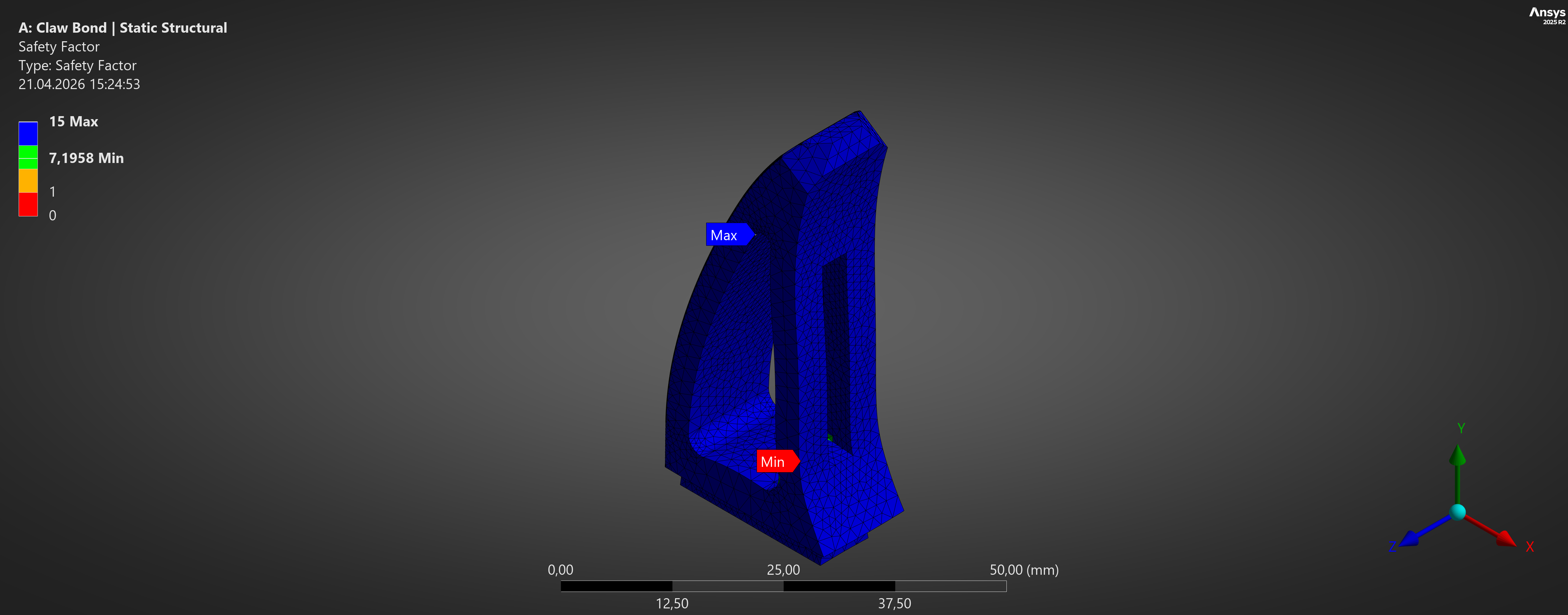
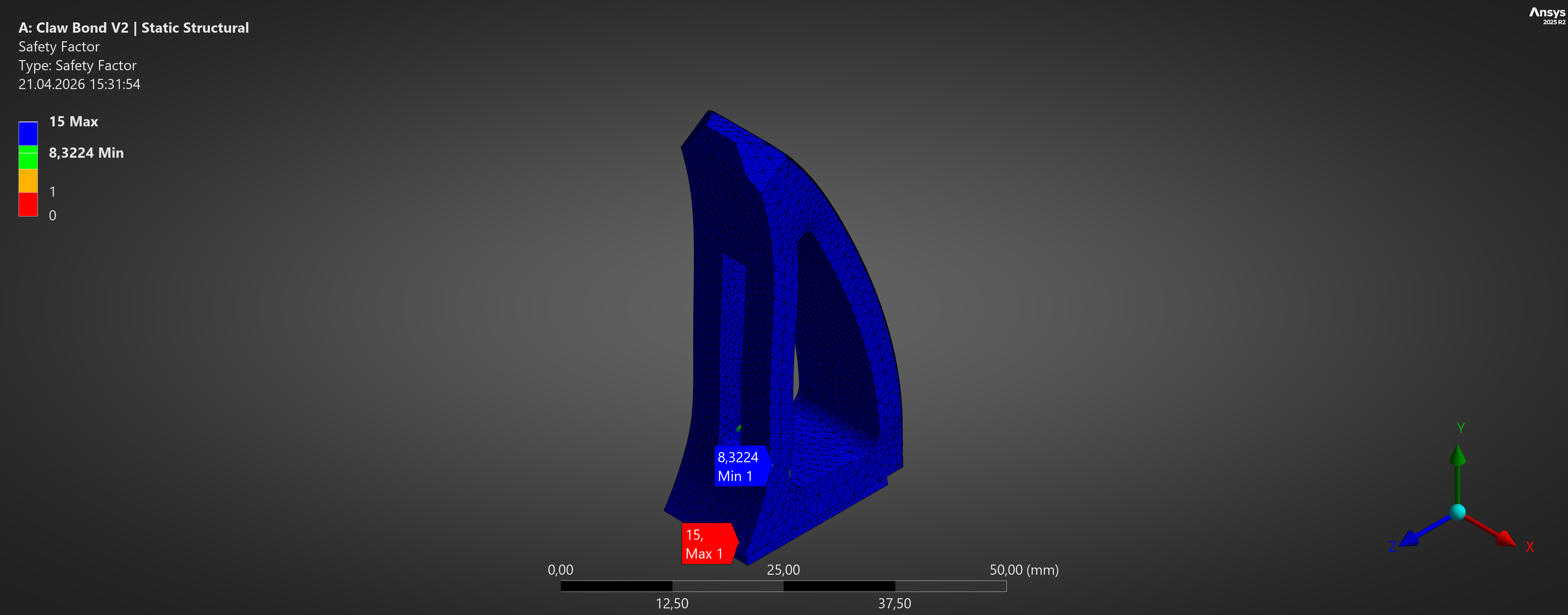
| Minimum Fatigue Safety Factor | 7.1958 | 8.3224 |
The fatigue results indicate that both geometries operate in a high-cycle regime at the selected load level. However, the final design improved the minimum fatigue safety factor by approximately 15.66%, which supports the structural improvements already observed in the static analysis.
V1 Baseline Fatigue Safety Factor Result
V2 Final Fatigue Safety Factor Result
Discussion
The baseline design was not a weak part in absolute terms; even the original geometry already showed a high fatigue life under the selected loading scenario. For that reason, the redesign did not create a dramatic change in predicted life or damage. Instead, its value appeared in the local stress redistribution: the critical hotspot was relieved, peak stress dropped, strain dropped, and the fatigue safety margin increased. This makes the redesign meaningful from an engineering point of view. The geometry was not overhauled. Instead, a few local transitions were improved in a way that produced a measurable structural benefit while preserving the original loading concept.
V1 Baseline Stress Hotspot
V2 Final Stress Hotspot
Note. Both plots are shown with individually scaled contours; comparison should be interpreted using the reported maximum stress values.
Final Technical Conclusion
Small local geometry changes produced a measurable structural benefit: lower stress, lower strain, slightly lower deformation, and a higher fatigue safety factor under the same load case.
About
Mechanical engineer focused on mechanical design, CAE, and engineering analysis. This portfolio presents selected projects in FEA, simulation, optimization, and design iteration, with applications related to manufacturing, automation, and robotics.
Skills
Tools
SolidWorks ANSYS Mechanical Python Arduino VBACore Areas
Mechanical Design CAE FEA Engineering Analysis OptimizationRelated Areas
Automation AI Applications RoboticsResume / LinkedIn / Contact
Resume: Add your resume PDF link
LinkedIn: https://www.linkedin.com/in/taylandaldal/
Email: daldaltaylan@gmail.com